Shared facilities
Counterflow burner
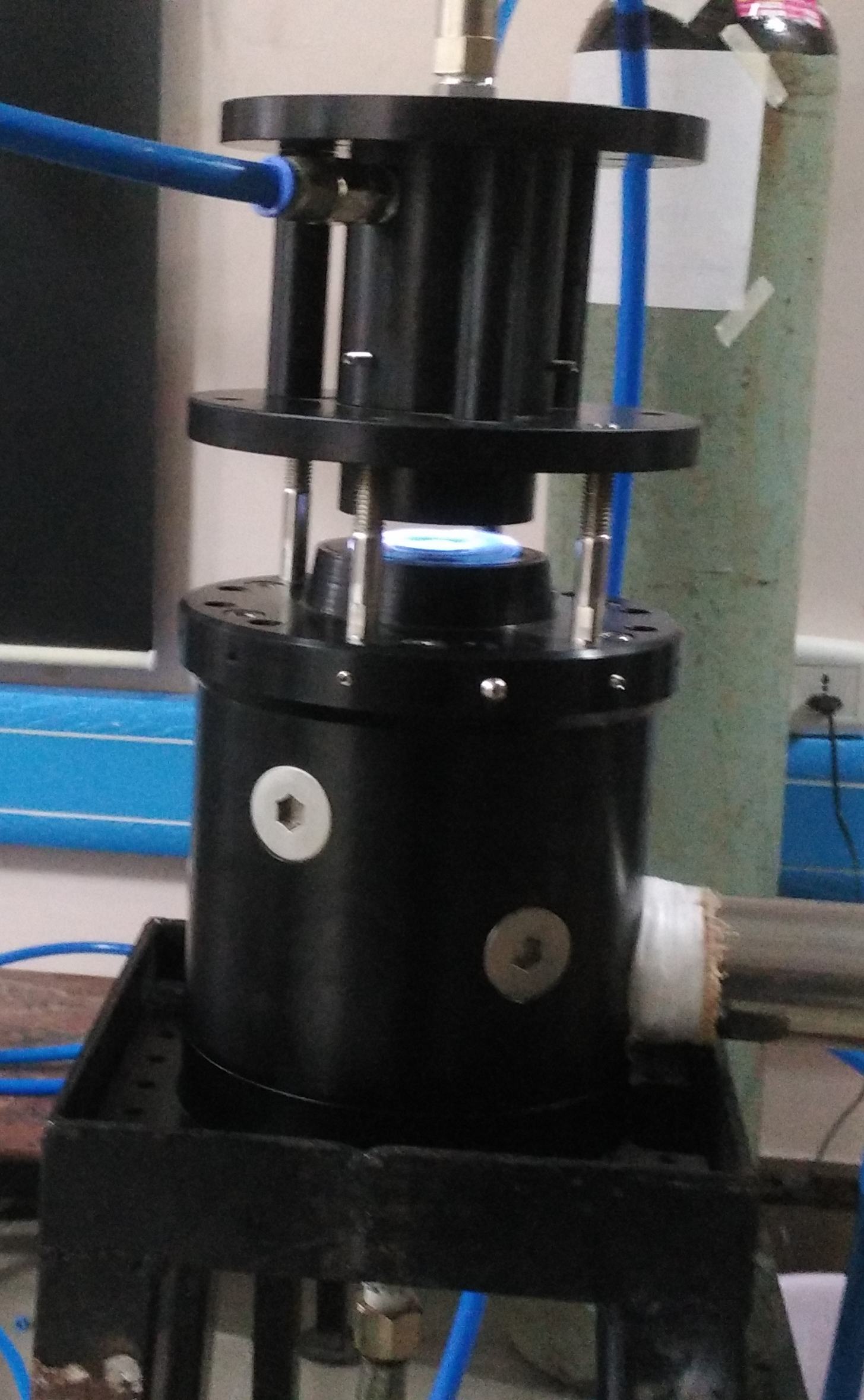
The counter-flow burner setup consists of fuel (bottom) and oxidizer (top) ducts, kept co-axially opposing each other. The fuel duct (df = 25.4 mm) is surrounded by two concentric annular ducts. Nitrogen is supplied through the inner annular gap in order to minimize the effect of ambient interference. The outermost annular duct is connected to an exhaust system, which facilitates the suction of the hot product gases. The outer walls of this duct are provided with water spray nozzles (type BETE PJ15) to cool the hot product gases and thereby prevent their autoignition in the exhaust duct. Water is supplied to the spray nozzles through a mini centrifugal pump (TULLU AC-30). The oxidizer duct (dox = 25.4 mm) is surrounded by a concentric duct through which nitro- gen is supplied, similar to that used in the fuel duct. Plug-flow boundary condition is ensured by placing multiple stainless steel wire screens (200 meshes/inch) near the exits of both fuel and oxidizer ducts. The flow rates of DME, air and ni- trogen are controlled using rotameters (with an uncertainty 2% of full scale reading). The fuel and nitrogen are mixed in a cylindrical mixing chamber of diameter 50 mm and length 200 mm. A sriees of fine stainless steel meshes are arranged inside the mixing chamber in order to ensure a homogeneous mixture. The counter-flow burner setup used in the present work is manufactured at UCSD and an exactly similar setup has been previ- ously used by the UCSD group to measure the extinction and auto- ignition characteristics of several fuels.

Counter-flow burner setup
Faculty incharge:
Dr. Krithika Narayanaswamy & Dr. V. Raghavan