Box of turbulence
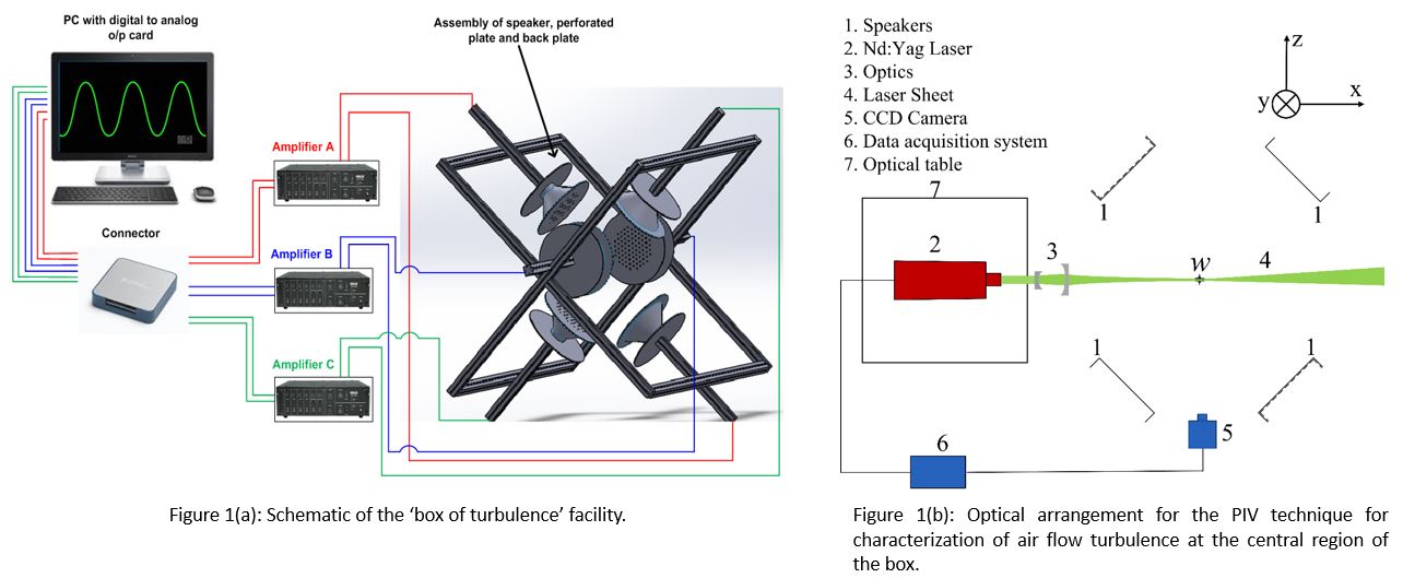
Figure 1(a) shows schematic of the ‘Box of Turbulence’ rig which is used to generate statistically stationary zero-mean homogeneous and isotropic turbulence (HIT) at the central volume of the box under atmospheric conditions. The HIT is achieved by high-efficient mixing of arrays of synthetic air jets. As depicted in the below figure, the turbulence rig consists of three pairs of loud speakers arranged on aluminum rails in such a way that the loudspeakers in each pair are oppositely faced and directed towards the center. Rubber pads were kept between speakers and back plate for vibration isolation. Perforated plates containing a two-dimensional array of 80 holes of 6 mm diameter (organized in a specific pattern) were fitted on top of each loud speakers such that operation of the loudspeakers generate high velocity synthetic turbulent jets from the surface of each plate. Each loud speaker was driven by a sine waves (frequency 50 Hz) generated by a 16 bit National Instruments analogous output card with eight channels out of which six channel are used in the current study. The signals from the output channel of the PCI card were amplified using three two channel amplifiers. Once actuated by the amplified signals, each loudspeaker generate an array of synthetic jets. Because of the inherent tolerance limits in the output of all electronic devices, appropriate balancing of the input voltage to each speakers requires hit and trial method which was done by operating two ‘Master control’ knobs on each amplifiers to produce same velocity jets from all speakers. The synthetic air jets interfere at central region and as a result of mixing, the zero-mean isotropic turbulence is generated. Different turbulent intensity/kinetic energy can be realized at the center of the box by controlling the voltage input to the speakers via the ‘Master control’ knobs in the amplifiers. The air flow turbulence at the center of the box was characterized by two-dimensional digital Particle Image Velocimetry (PIV). Figure 1(b) shows a schematic of the plan view of the facility and the optical arrangements for PIV.

Setup to produce homogeneous and isotropic turbulence
Faculty incharge:
Dr. Srikrishna Sahu